How to Use CAD to Design the Perfect Workbench: A Step-by-Step Guide
Discover how to transition from messy paper sketches to precision 3D models. Learn parametric CAD techniques to design a flawless, custom woodworking workbench.
Mar 25, 2026 - Written by: Linda Wise

I remember the exact moment I stopped designing woodworking projects on graph paper. I was staring at a pile of premium hard maple, a set of hand-drawn blueprints covered in coffee stains, and a glaring math error that had just cost me $150 in ruined lumber. The leg tenon was supposed to be offset by an inch to clear the tail vise hardware. I forgot to carry a fraction. The wood was scrapped.
That was the day I realized something fundamental: your workbench is the heart of your shop, the central datum from which all your future accuracy flows. If you rely on guesswork to build the bench itself, you are building a foundation on quicksand.
Transitioning to Computer-Aided Design (CAD) entirely alters the trajectory of your woodworking. I’ve personally found that simulating a build in a digital environment before ever turning on the table saw eliminates the anxiety of the initial cut. You aren’t just drawing shapes; you are defining kinetic relationships, testing structural tolerances, and mapping out complex joinery in a risk-free vacuum.
If you are ready to design a bench that will outlast you, this guide will walk you through the precise, step-by-step process of modeling it in CAD.
Quick Comparison: Top Picks for Digital Drafting
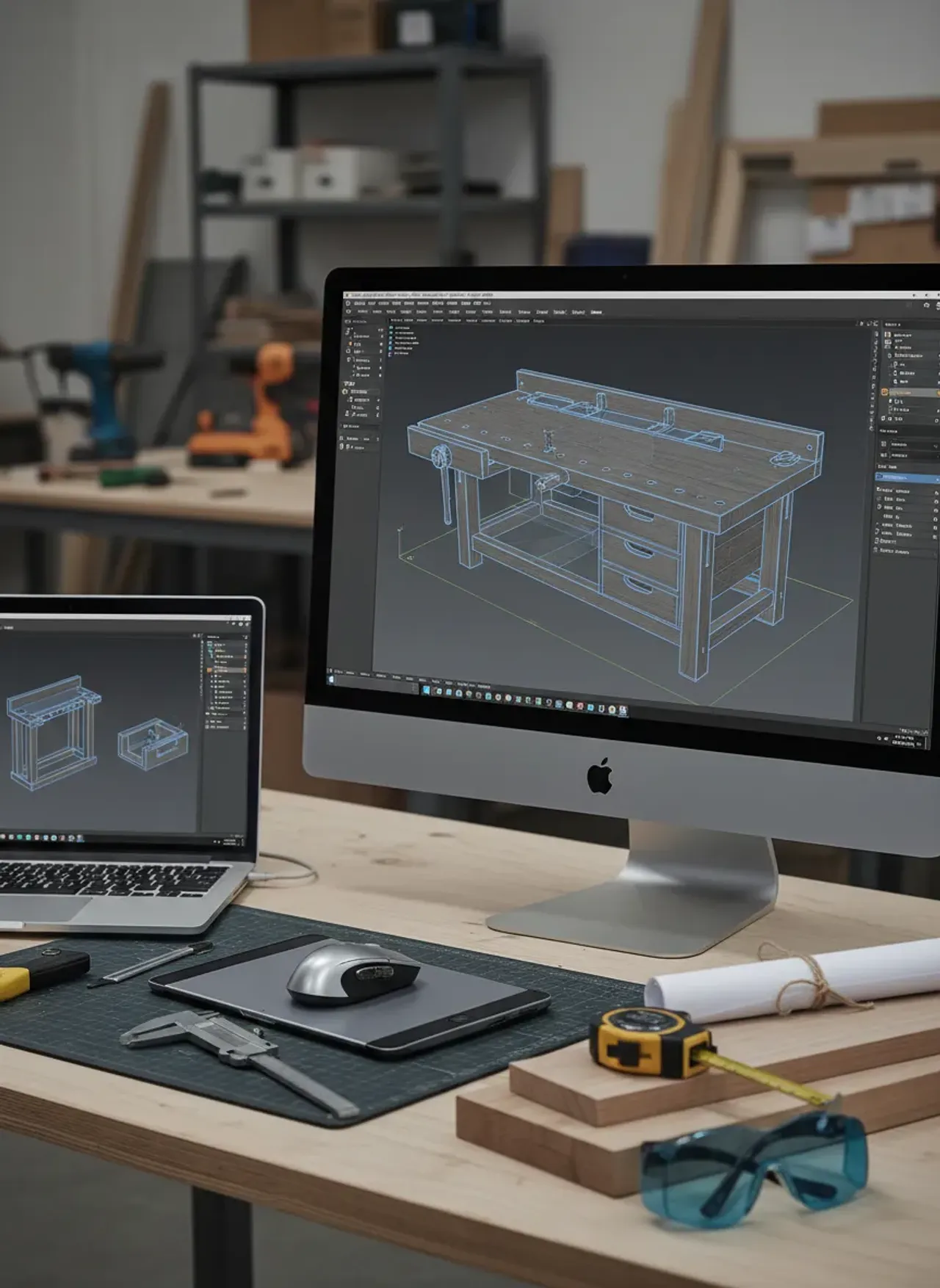
Before we plunge into parametric modeling, you need the right hardware to interact with the software smoothly. Trying to navigate 3D space with a trackpad is an exercise in pure frustration. Here is my current desk setup for CAD work.
| Product | Rating | Check Price |
|---|---|---|
| 3Dconnexion SpaceMouse Wireless | ⭐⭐⭐⭐⭐ | View on Amazon |
| Mitutoyo 500-196-30 Digital Caliper | ⭐⭐⭐⭐⭐ | View on Amazon |
| Dell UltraSharp 27-inch 4K Monitor | ⭐⭐⭐⭐½ | View on Amazon |
Phase 1: The Philosophy of Digital Joinery
Why go through the trouble of learning complex software just to build a table? Because a workbench isn’t a table. It is a three-dimensional clamping surface built to withstand immense lateral force.
When you hand-plane a rough board, you are pushing hundreds of pounds of kinetic energy across the top. If your bench lacks mass or rigid joinery, it will rack, shimmy, and walk across your shop floor. CAD allows you to visualize the structural integrity of your design. You can zoom inside a blind dovetail to ensure it seats perfectly. You can rotate the model to see if your bench dogs will accidentally intersect with your leg stretchers—a classic mistake that ruins many first-time builds.
Think of digital modeling as spatial insurance. You are pre-building the bench. You identify the clashes, the weak points, and the material constraints in a space where fixing a mistake takes a simple Ctrl+Z rather than a trip back to the lumberyard.
Phase 2: Defining Your Physical Parameters
Before opening your software, you have to lock down the physical constraints of your workspace and your body. CAD is entirely literal. It will build exactly what you tell it to, regardless of whether it actually fits in your garage.
Ergonomics and the “Pinky Knuckle” Rule
Bench height is deeply personal. A bench meant for heavy hand-tool work (planing, chiseling) should be lower, allowing you to get your body weight over the tool. A bench meant primarily for power tool assembly or routing should be higher to save your lower back.
Here is the real kicker: the golden rule for a hand-tool bench is the “pinky knuckle” measurement. Stand straight with your arms relaxed at your sides. The distance from the floor to your pinky knuckle is your baseline bench height. Write this number down. It will become your first parametric variable.
Spatial Integration
You also need to map out your shop’s footprint. Just as you would carefully measure an entryway to ensure hall trees and mudroom lockers fit harmoniously without blocking high-traffic zones, your workbench must sit in a functional orbit. Leave at least three feet of clearance on all sides to allow for maneuvering long boards.
Pro Tip: When defining your dimensions, design the bench top to be slightly narrower than your standard doorway (typically 30 to 32 inches). You never know when you might move shops, and a 36-inch deep Roubo bench requires a chainsaw to get through a standard residential door.
Phase 3: Selecting Your CAD Software
Woodworkers generally gravitate toward two platforms. Both are phenomenal, but they require entirely different mindsets.
SketchUp: The classic choice. It operates on direct modeling. You draw a rectangle, pull it into a 3D box, and snap pieces together. It’s highly intuitive, visual, and fast. However, if you decide halfway through the project that your bench legs need to be 4 inches thick instead of 3, you often have to manually adjust multiple intersecting components.
Fusion 360 (or SolidWorks): My personal preference. These are parametric modelers. Instead of just drawing a box, you assign constraints and variables. You tell the software, “Leg thickness = X.” If you change X later, every single piece of joinery connected to that leg automatically recalculates and updates. The learning curve is steep, but the power is absolute.
For the rest of this guide, I will outline the workflow using parametric principles, as it represents the most bulletproof way to design complex furniture.

Phase 4: The Step-by-Step Modeling Workflow
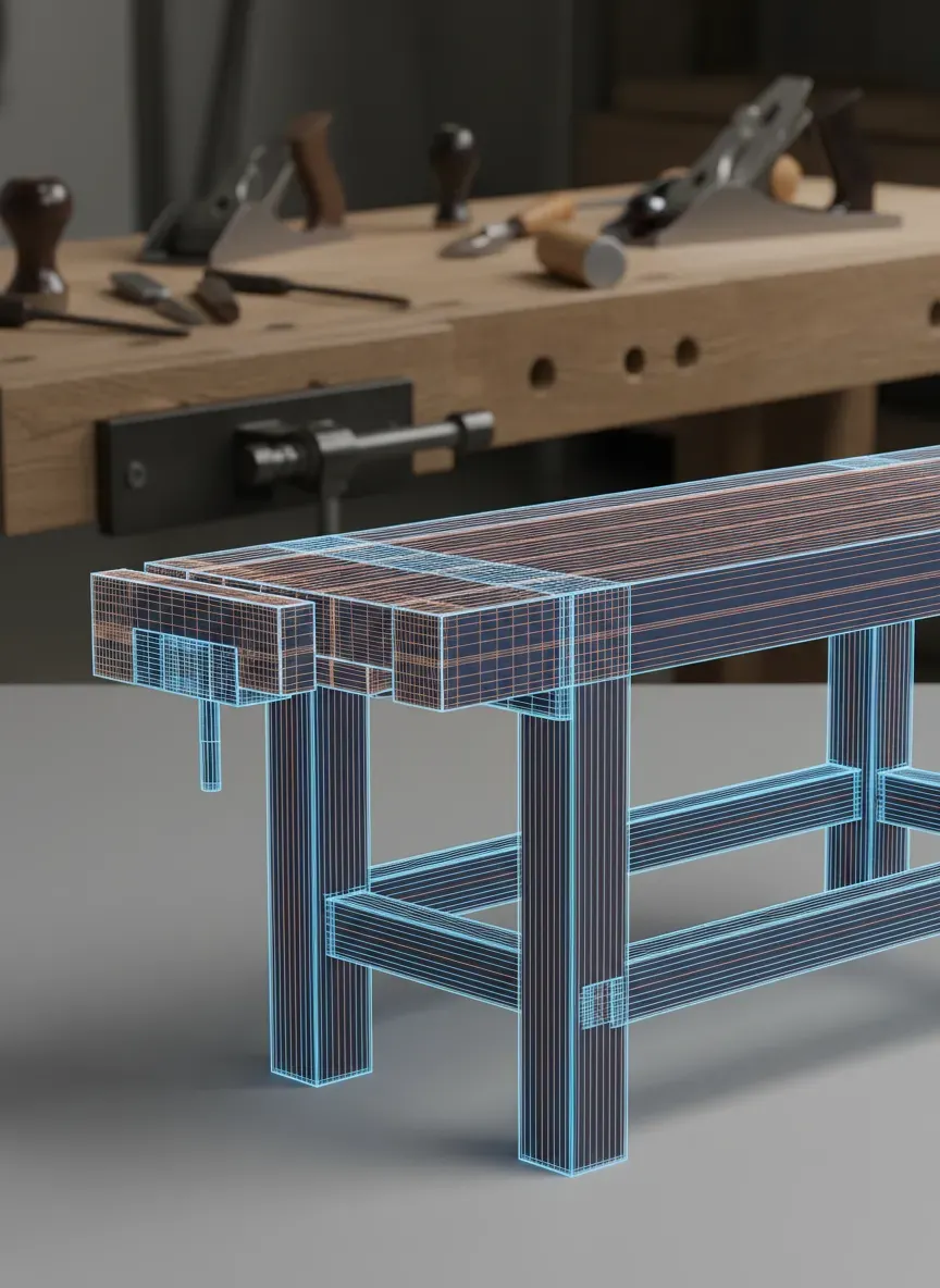
Let’s get our hands dirty. Boot up your software. We are going to design a modified Roubo-style workbench, known for its massive top and flush front legs.
Step 1: Establish Your User Parameters
Do not draw a single line yet. Open your parameter settings and define your variables. This is the secret to elite CAD modeling. Create variables for:
Bench_Length: 72”Bench_Width: 24”Bench_Height: 34”Top_Thickness: 4”Leg_Thickness: 5”Overhang: 12”
By setting these up first, your entire design becomes fluid. If you later realize 72 inches won’t fit your shop, you change the number to 60, and the entire 3D model scales proportionally without breaking.
Step 2: Drafting the Massive Top
Start a new sketch on the top-down plane.
- Draw a center-point rectangle.
- Dimension the length using your
Bench_Lengthvariable. - Dimension the width using your
Bench_Widthvariable. - Extrude this sketch upward using the
Top_Thicknessvariable.
You now have a monolithic slab. But woodworkers don’t build out of monoliths; we laminate strips. While you could model each individual 2x4 you plan to glue up, it clutters the timeline. Treat the top as a single solid component for now, but apply a wood grain material map to it so your brain registers it as timber.
Step 3: Engineering the Base and Legs
Create a new sketch on the bottom face of your slab. This is where we define the leg placement.
- Draw rectangles for the four legs.
- Lock their front faces so they are completely flush with the front edge of the bench top. This is critical for workholding; you want to be able to clamp wide boards across the face of the leg and the edge of the top simultaneously.
- Extrude the legs downward. The extrusion distance should be:
Bench_Height - Top_Thickness. This formula ensures that no matter how you alter the top thickness later, the total height remains exactly what you want.
Step 4: Stretchers and the Mortise & Tenon
Legs alone will wobble. You need stretchers connecting them, typically a few inches off the floor.
- Sketch your stretchers connecting the legs.
- Now, the joinery. We need to create mortises (holes) in the legs, and tenons (pegs) on the stretchers.
- In CAD, you first model the stretchers overlapping into the legs by your desired tenon length (say, 2 inches).
- Use the “Combine” or “Boolean” tool. Select the Leg as the target body, and the Stretcher as the tool body. Set the operation to “Cut” and make sure to “Keep Tools”.
Instantly, the software carves a perfect mortise out of the leg that perfectly matches the stretcher.
Step 5: Incorporating Hardware and Vises
A workbench without vises is just a heavy desk. Whether you are installing a traditional tail vise, a cast-iron front vise, or a modern leg vise with a crisscross mechanism, you need to account for the metal.
Most premium hardware manufacturers (like Benchcrafted or Yost) offer downloadable 3D CAD files (STEP or IGES format) of their products. Download these and import them into your assembly.
Position the vise hardware exactly where you want it. This allows you to precisely locate where to drill your mounting holes and where to route out mortises for the vise tracks. You will immediately see if a massive lag screw is on a collision course with one of your wooden tenons.
Phase 5: Simulating and Refining the Model
With the broad strokes done, we enter the refinement stage. This is where CAD pays for itself.
The Dog Hole Array
Bench dogs are metal or wooden pegs that drop into holes in the top to secure workpieces. You need an array of 3/4-inch holes running along the front edge of the bench, aligned with your tail vise.
Model a single 3/4-inch cylinder, drop it through the top, and use a rectangular pattern tool to duplicate it every 3 inches.
Now, look underneath the bench. Did one of those holes drill straight through the top of your leg tenon? If so, you’ve discovered a structural compromise before touching a drill press. Shift your dog hole array half an inch to the left to clear the joinery. Crisis averted.

Interference Detection
Most advanced CAD programs have an “Interference” or “Clash Detection” tool. Run it. The software will highlight any areas where two solid bodies occupy the same digital space. In woodworking, unless it’s a tight friction-fit joint, overlapping parts mean you made a mathematical error. Resolve these red zones until the software gives you a clean bill of health.
Tolerances and Glue Gaps
Digital space is perfect; the physical shop is not. Wood needs room for glue. If you machine a tenon to be exactly 1.000 inches thick and a mortise to be exactly 1.000 inches wide, the friction will starve the joint of glue and likely split the leg.
Use the “Push/Pull” or “Offset Face” tool to widen your mortises by about 0.005 to 0.010 inches on the cheeks. This models the tiny reservoir needed for liquid hide glue or PVA.
Phase 6: From Screen to Sawdust
A beautiful 3D model is useless if you can’t translate it to the shop floor. The final step of the CAD process is generating documentation.
Generating the Cut List
Because you modeled your bench as individual components (Top, Leg_Front_Left, Stretcher_Long, etc.), you can extract a precise bill of materials (BOM). Plugins like MapBoards Pro for Fusion 360 or CutList for SketchUp will automatically read your components, lay them out flat on digital sheets of plywood or rough lumber, and calculate exactly how many board feet you need to buy.
Creating Orthographic Drawings
Jump into the 2D Drafting environment of your software. Create views of your bench: Front, Top, Side, and an Isometric perspective. Pull dimensions onto the paper. Print these out on large 11x17 paper.
Keeping your shop environment organized while executing these plans is essential. Just as you’d rely on smart shoe storage solutions to keep a mudroom free of tripping hazards, you need a system for stacking your freshly milled workbench parts. Label every piece of physical wood with chalk to match the component name generated in your CAD cut list. Clear the floor. A safe shop is a precise shop.
Key Takeaways for CAD Woodworking
- Embrace Parameters: Always use variable-driven dimensions for the overall height, width, and length.
- Model the Hardware: Never guess the clearance of a vise. Import the exact 3D model from the manufacturer.
- Account for Real-World Physics: Leave digital gaps for glue, and account for wood movement across the grain when designing the end caps.
- Virtual Clashes Save Physical Cash: Always run interference detection before generating a cut list.
The Bottom Line
Taking the time to build your workbench inside a digital environment transforms the actual woodworking process from a stressful puzzle into a relaxing assembly. You are no longer guessing if the angles are correct or if the hardware will fit; you know it will, because you’ve already proven the math. Mastering CAD doesn’t replace the tactile joy of hand tools and wood shavings; it enhances it by removing the anxiety of catastrophic mistakes.
Here is the real kicker: sometimes you don’t want to spend 40 hours staring at a screen modeling joints. Sometimes, you just want to smell sawdust and start building immediately with plans that are already mathematically proven.
If you want to skip the intense digital drafting phase—or if you want incredibly detailed reference models to practice your CAD skills against—you need to check out Ted’s Woodworking. I’ve used their archive extensively. They offer over 16,000 meticulously crafted woodworking plans, including dozens of elite workbench designs (from classic Roubos to portable folding benches), complete with pre-calculated cut lists and step-by-step blueprints.
Right now, you can bypass the learning curve and grab the entire archive at a massive 75% discount. Stop guessing your dimensions and start building with absolute confidence by grabbing the plans here: Click here to get 16,000 Woodworking Plans at 75% Off.